On first glance, building an EV may seem like an odd case study to feature given my progression into the digital design and UX research fields. Nevertheless, I credit this high school passion project with instilling a strong interest in methodically decomposing problem spaces and working through ambiguous design challenges. These interest areas led me into the UX field in the first place and through further experiences have translated into some of my strongest skills I bring to each new problem space.
When beginning this project, the automotive scene looked very different than it does today. In terms of mass produced electric vehicles, the low to mid budget customer had a severe shortage of affordable zero emission vehicle options.
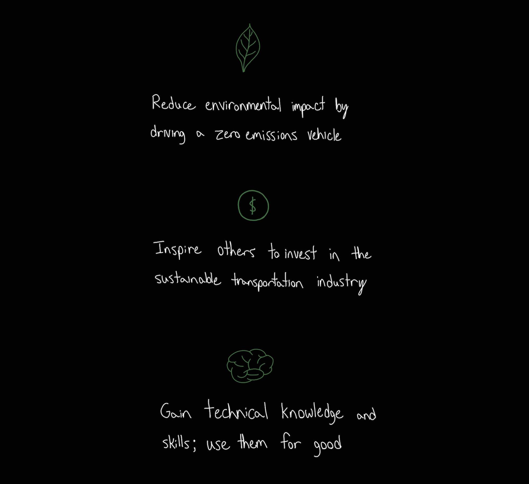
Without many commercial options, I landed on the idea of converting a combustion powered vehicle into an all-electric. My decision was based on three benefits tied to this solution:
Converting a vehicle requires an excellent understanding of how each vehicle system works. Don’t get me wrong, I drooled over car magazines growing up but I had no idea how they worked when it came down to the fine details. Nearly the first quarter of the project was spent developing a solid foundation of knowledge.
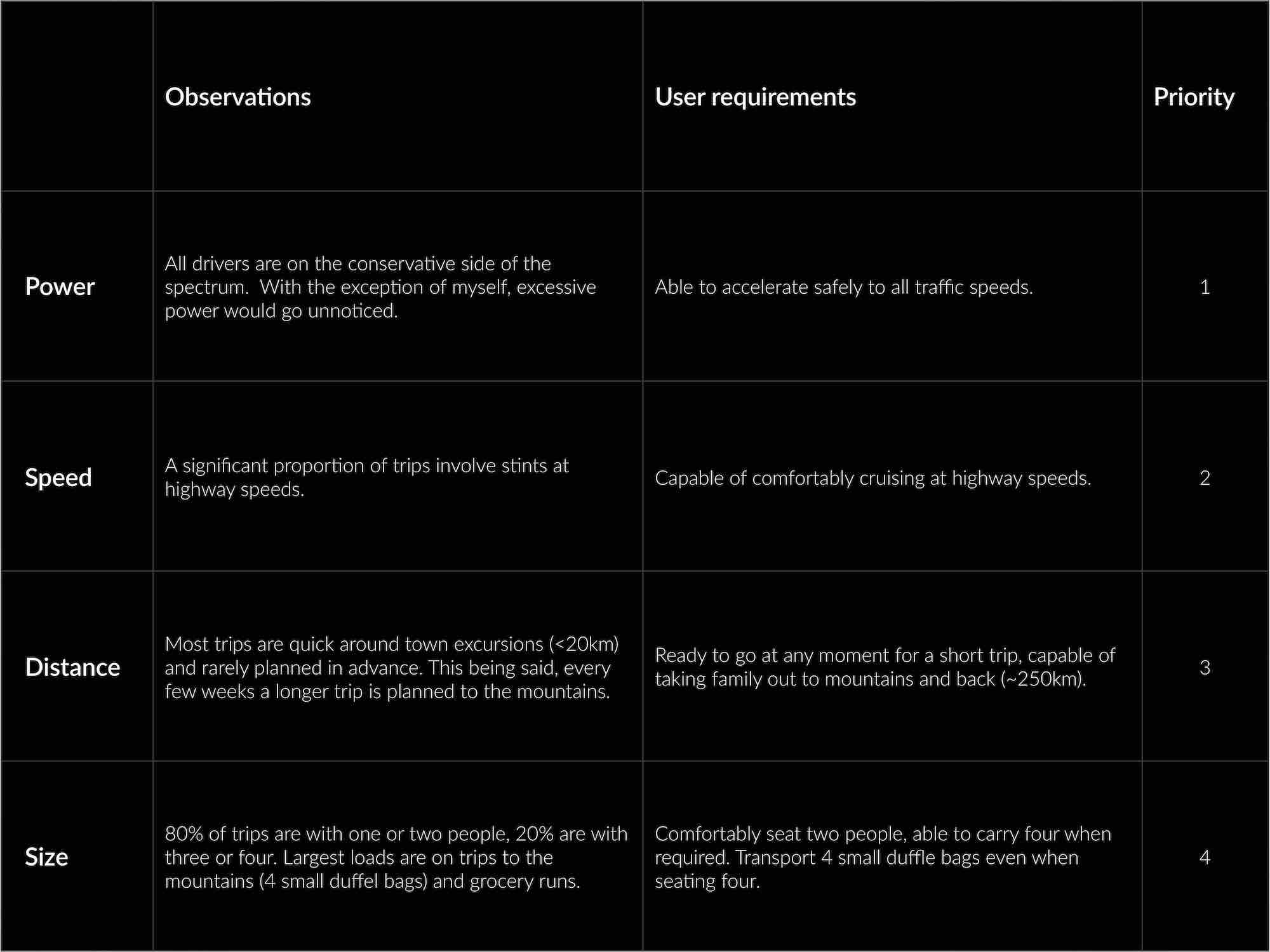
By analyzing my families (the end users) driving habits through ethnographic field studies and casual interviews, I learned what we saw as being important in a vehicle.
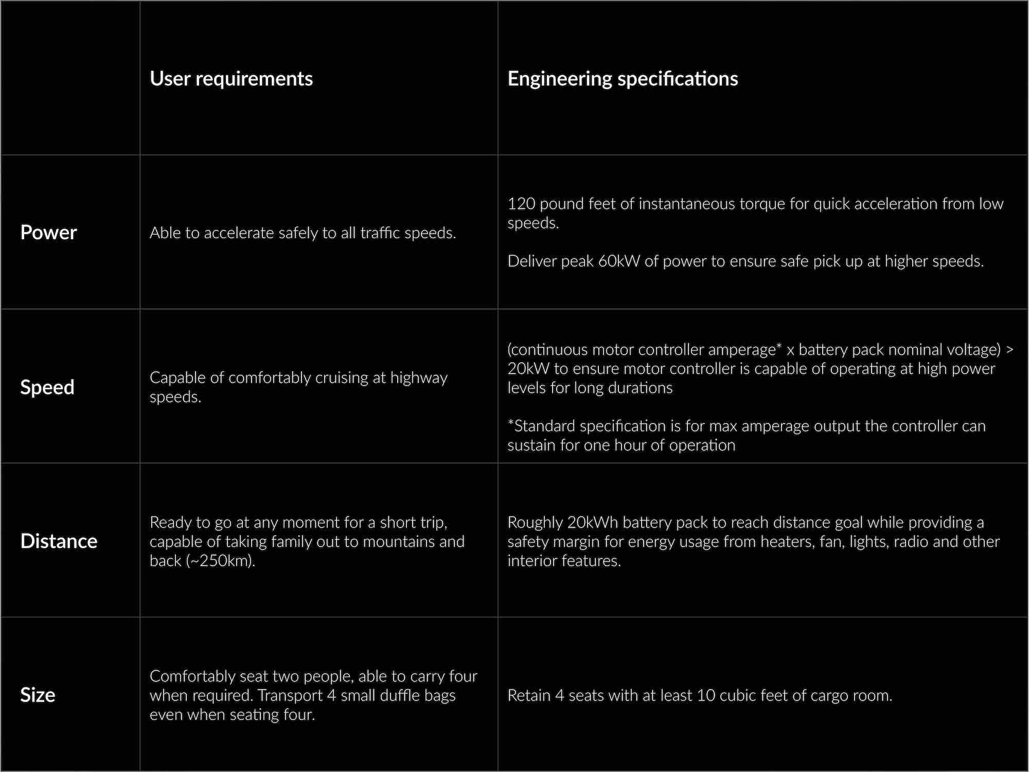
To make these requirements come to fruition, user requirements were turned into engineering specifications as each system was designed.
Once I knew the specifications each component needed to meet, I formed price ranges for all major parts and tools that would be required to complete the conversion.
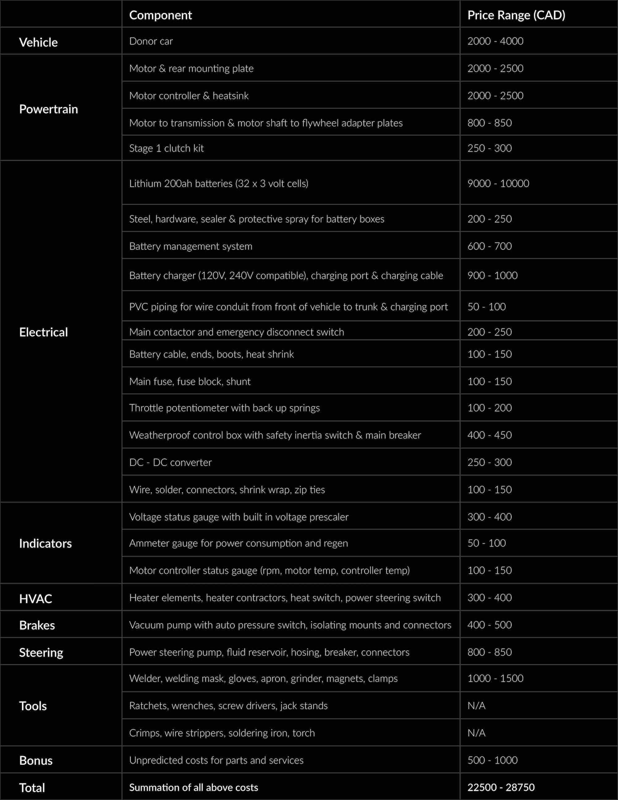
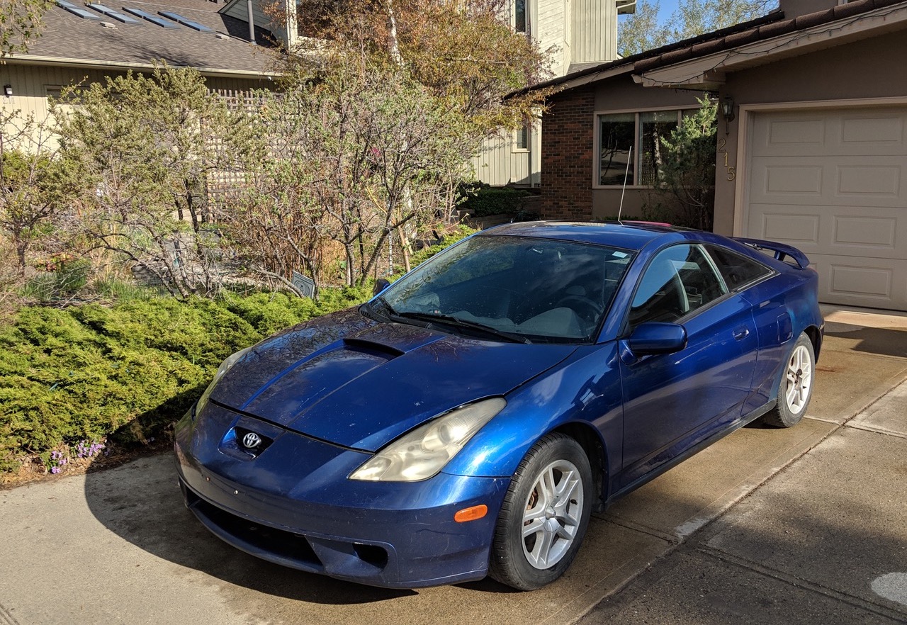
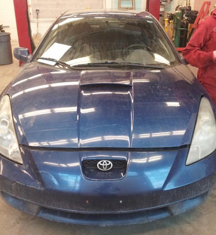
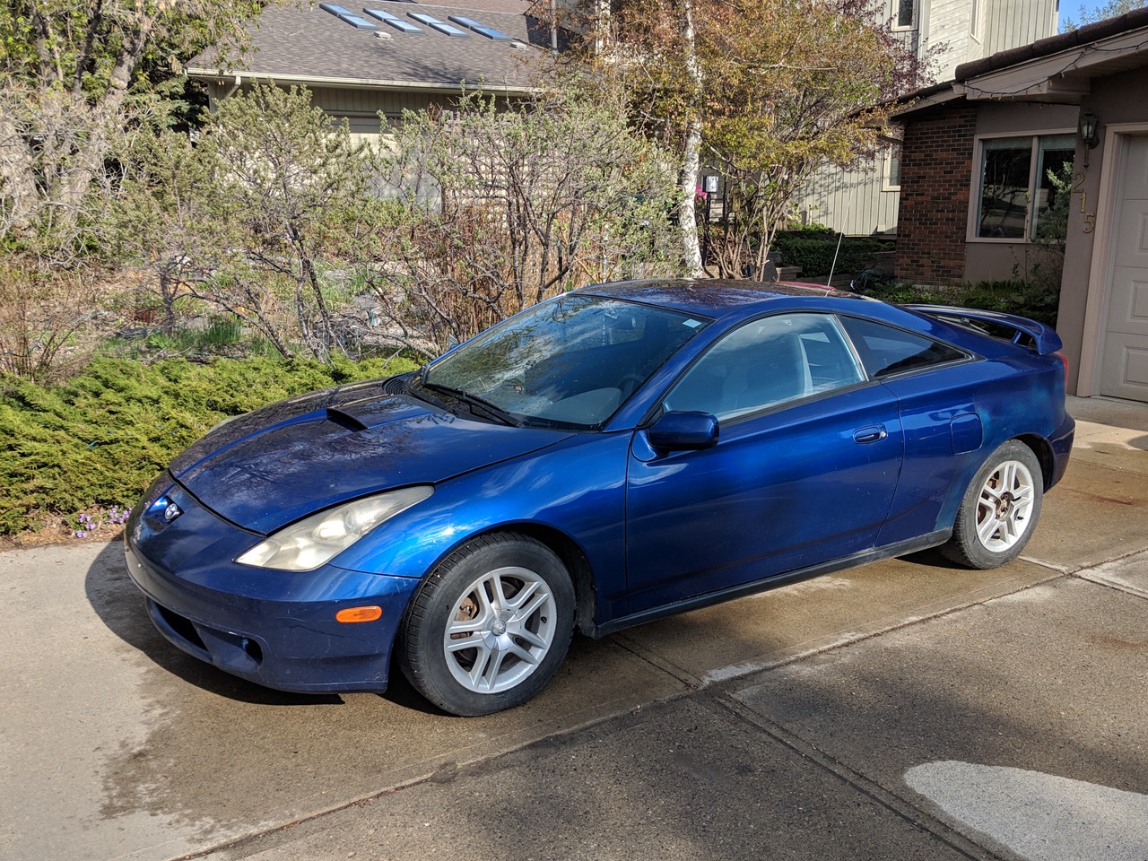
I put an emphasis on selecting a car that was small and light to reduce the size and power (and thus price) of the drivetrain components needed to achieve the performance goals outlined. In the realm of smaller cars, I narrowed in on the latest generation Toyota Celica. Despite being quite small, Celica’s have 4 seats, a large trunk and engine bay to distribute the battery pack's weight, and are built in a simple and reliable way.
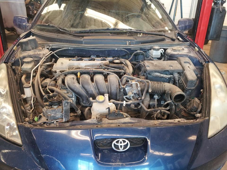
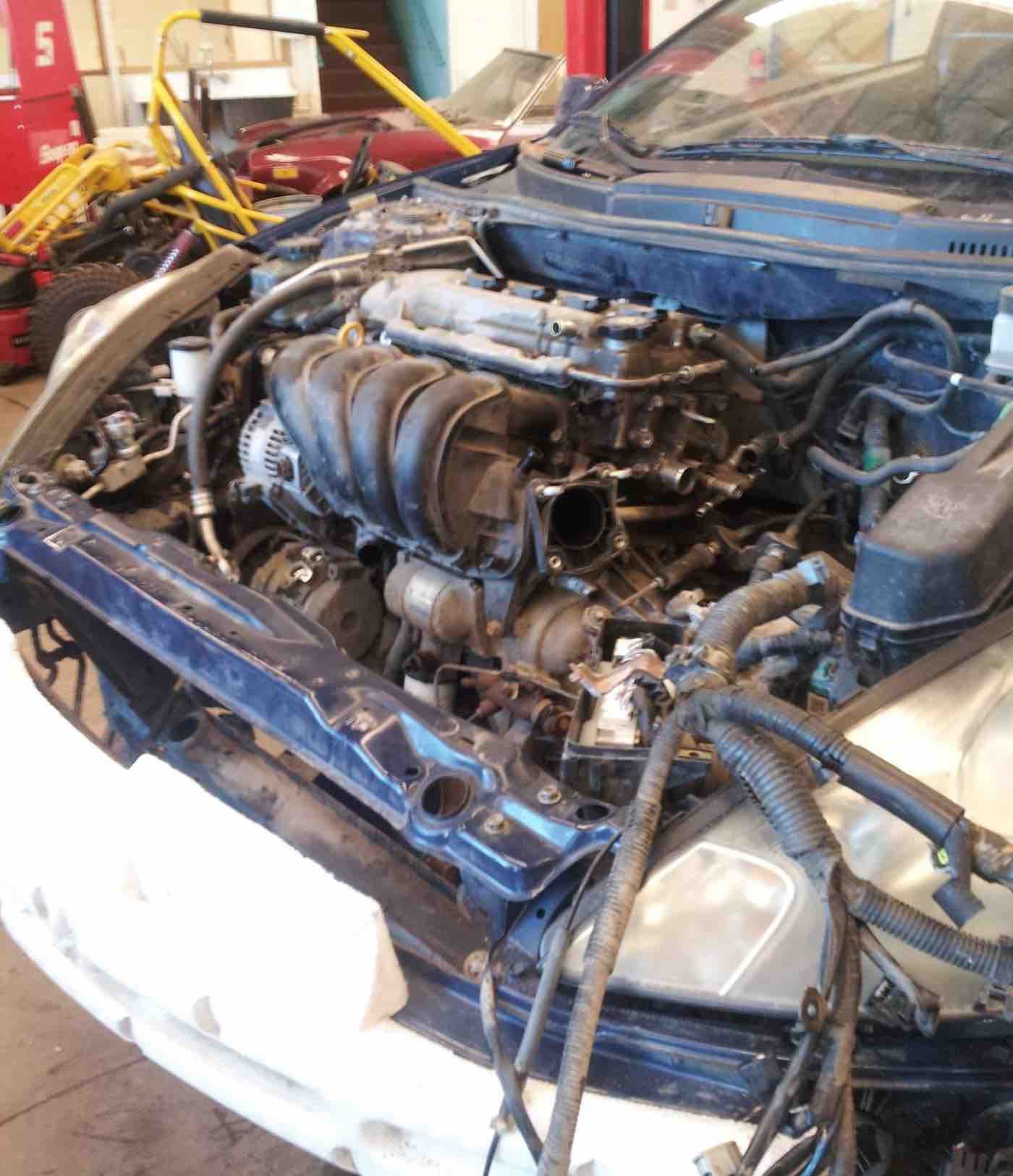
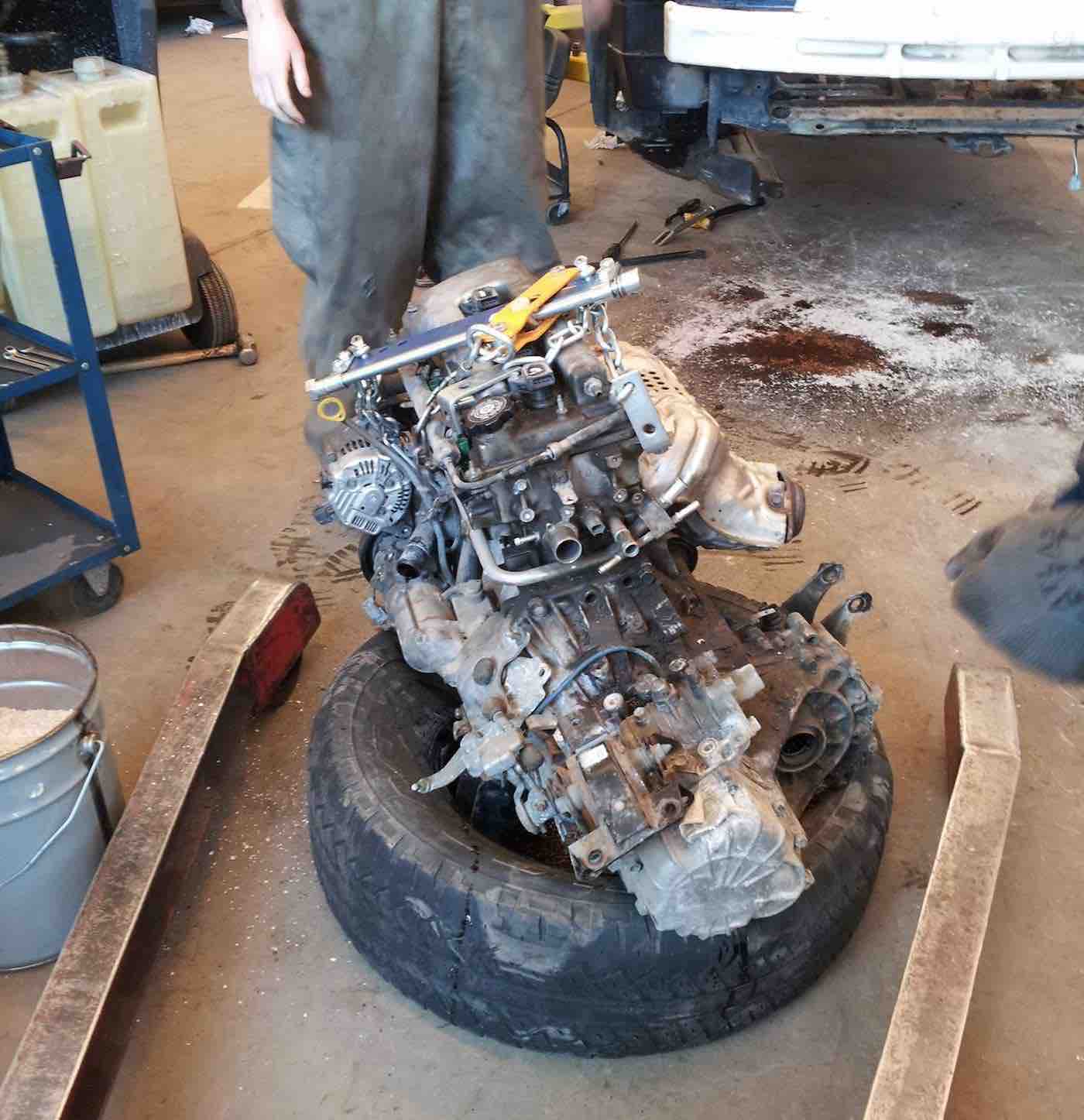
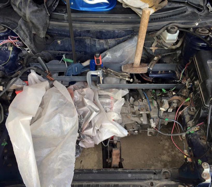
I had a base car to work off of, now what? To make room for the new electric drivetrain I removed the stock Toyota ZZ1 engine, ECU (engine control unit), radiators, exhaust, and fuel system. Unfortunately, that’s a little more complicated then it sounds. Combustion engines typically provide power through a serpentine belt to a number of different systems such as your vehicle's power brakes, power steering, and cabin heating system. Each disrupted system was then dismantled, analyzed and taken on as a separate design challenge.
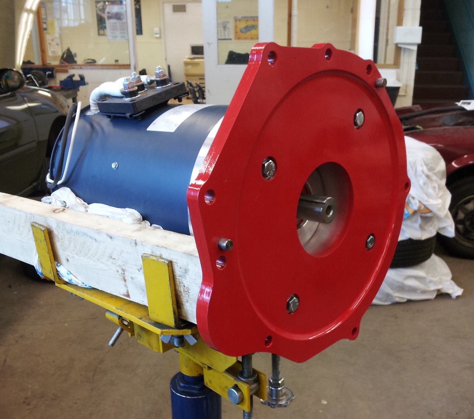
An AC motor was selected to allow for regenerative braking. By comparative analysis with the stock Toyota ZZ1 engines specs, the HPEV AC50 running at 96v and 650amps was a great candidate to achieve all the outlined project performance goals.
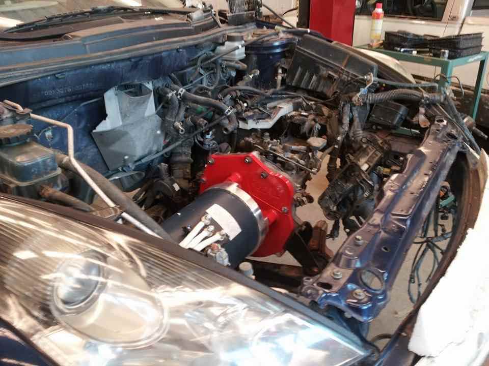
After removing the stock Toyota parts, I rebuilt the powertrain using an HPEV AC50 electric motor directly mounted to the stock transmission. I selected a manual transmission vehicle to simplify this conversion process. While there was a lot of flexibility in where certain components could go, the motor was not one of them. Positioning it early allowed other systems designs to be planned out around the motor's dimensions.
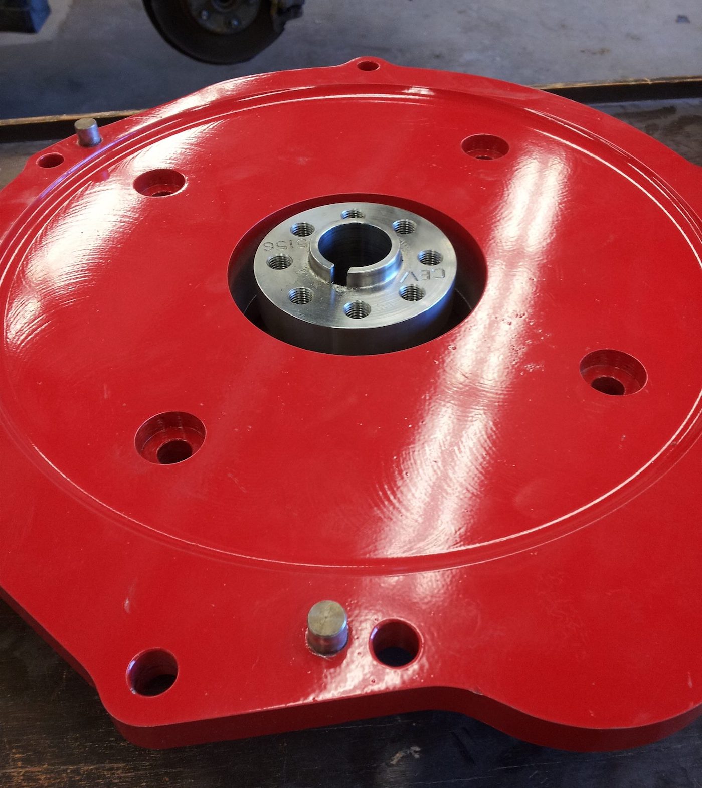
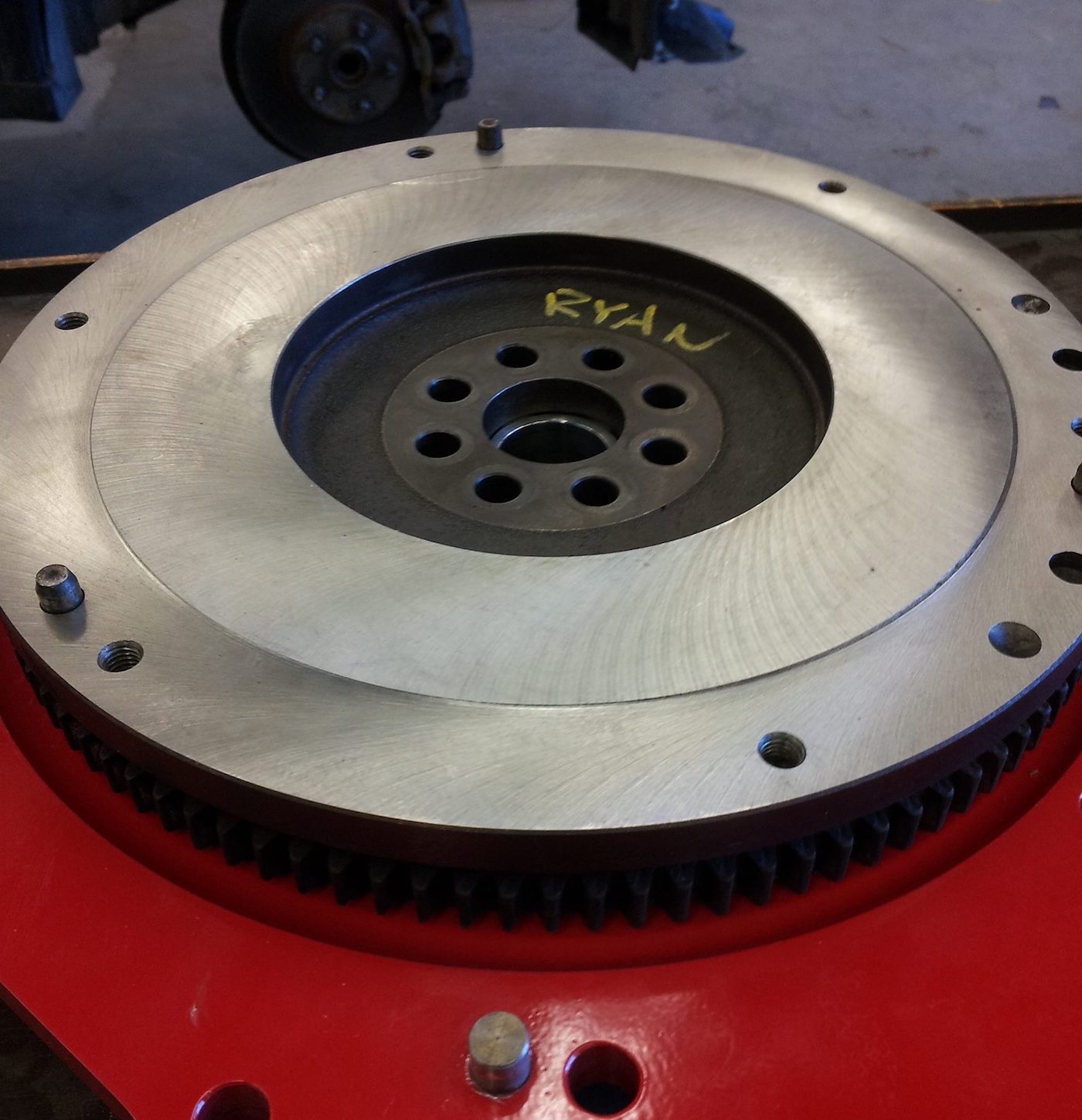
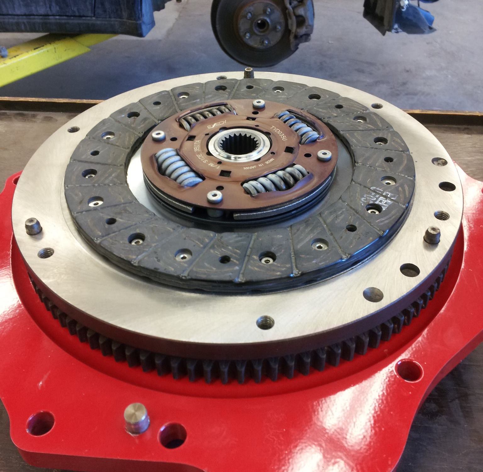
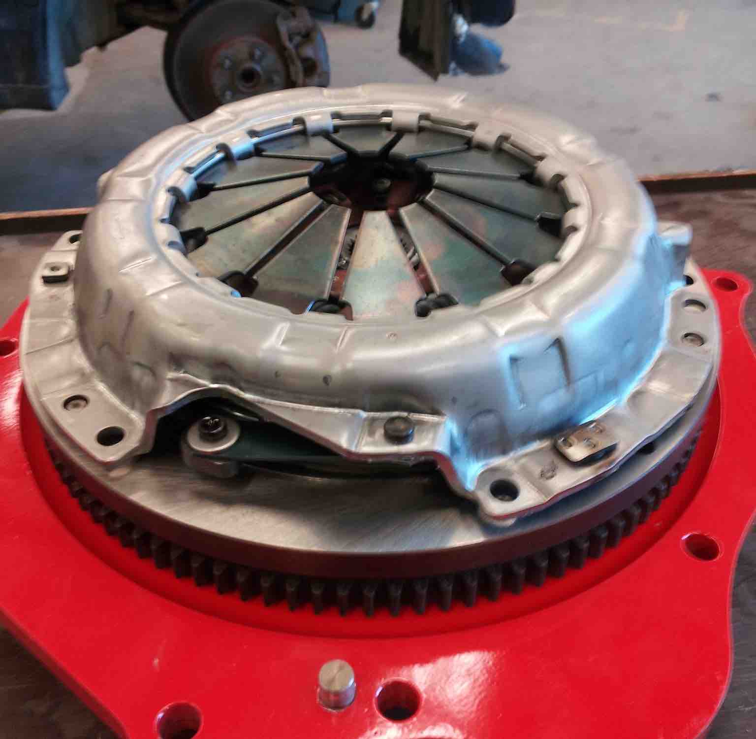
The motor’s keyed shaft was fitted with an adapter and mounted with the flywheel and clutch assembly. An upgraded stage 1 clutch was installed to better handle the instantaneous torque delivered from the new electric motor. With the clutch binding the motor shaft to the transmission and the axles linking the transmission to the wheels, the powertrain had a complete mechanical linkage.
If vehicles are not your forte, the basic gist is that at this point if the motor drive shaft rotates, so would the wheels. Based on what gear is selected by the driver, the wheels would spin at different speeds given the same motor shaft rotation speed.
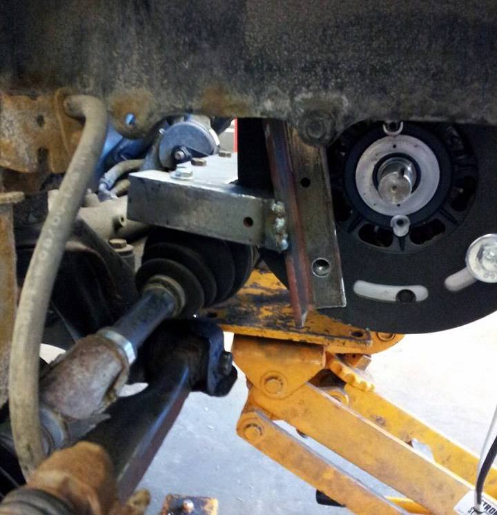
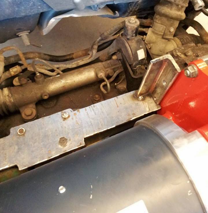
After bolting in the motor, I added a bracket to support the passenger half shaft and the rear end of the motor. A vibration isolating mount was used to fasten the bracket to the chassis and with that, the powertrain installation was complete.
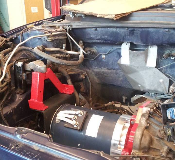
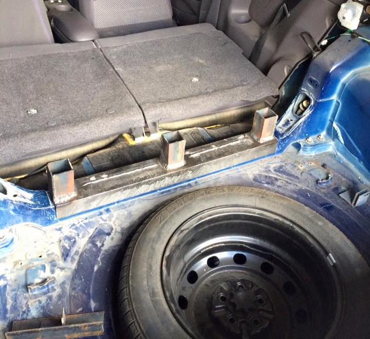
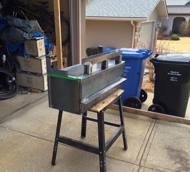
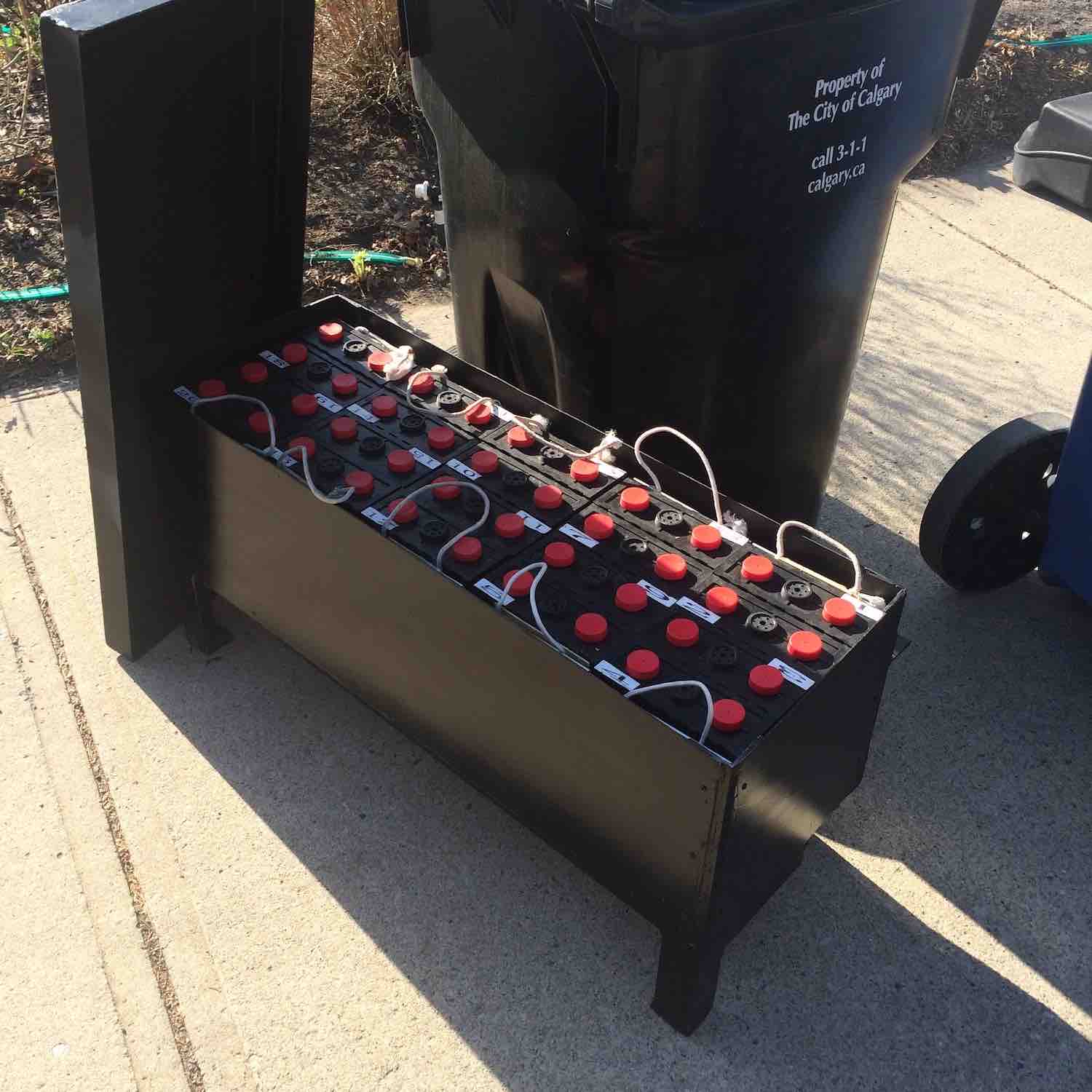
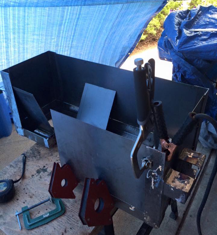
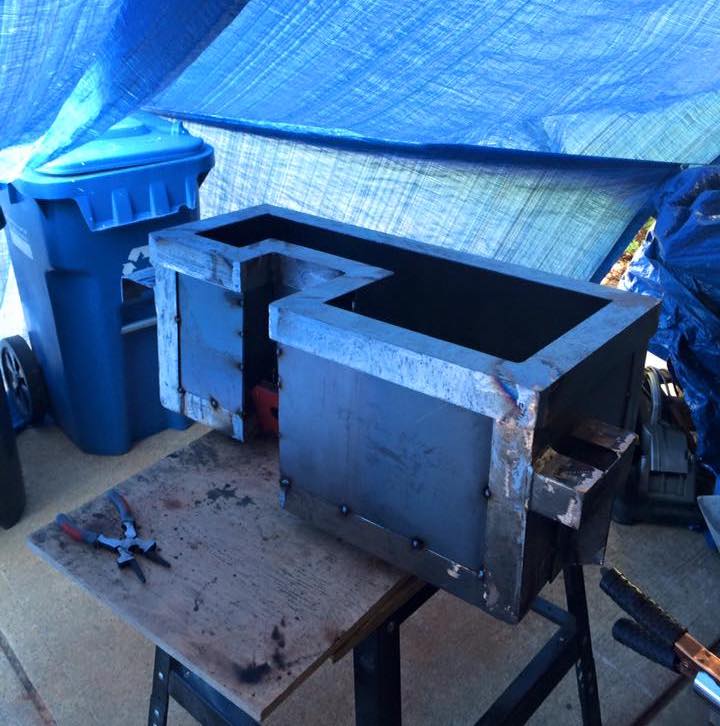
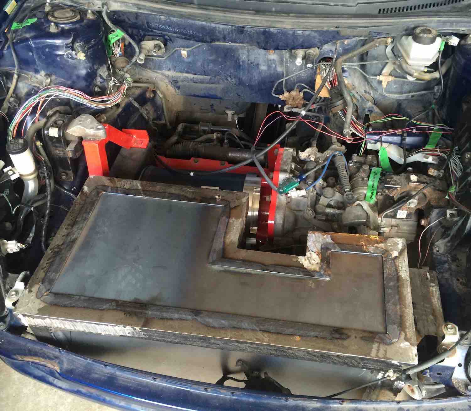
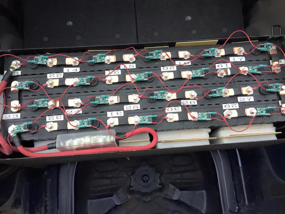
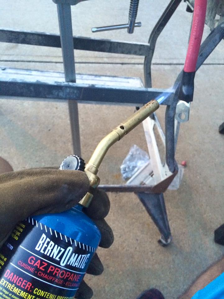
With a minimum requirement to travel 250km, I needed to fit 32 battery cells each at 3.0 volts and 200 amp hours into the vehicle. In order to keep all other electrical components in the engine bay, a maximum of 12 cells and a regular 12v battery were fitted into the front in a fabricated steel battery box. The remaining 20 cells were placed behind the back seat in their own separate fabricated box.
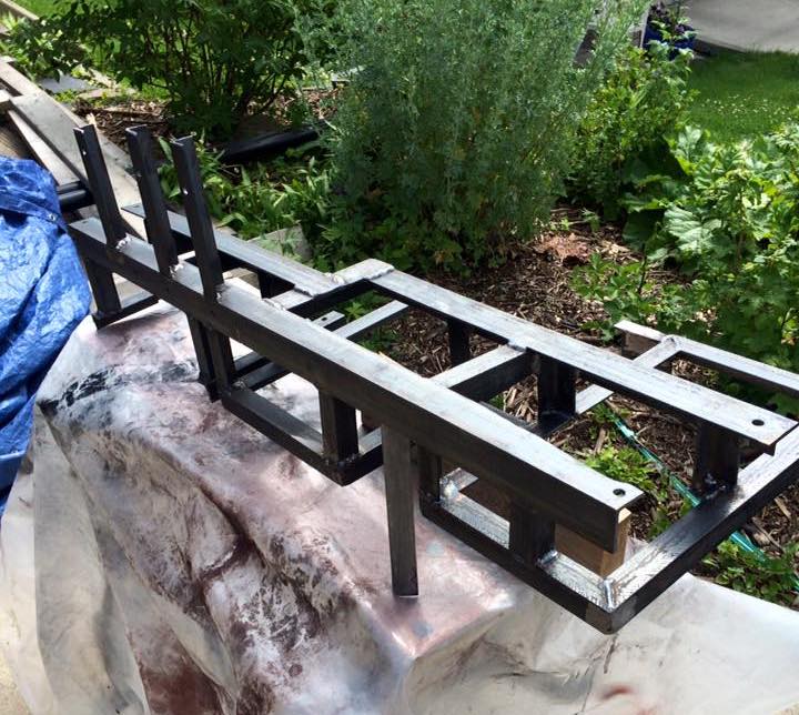
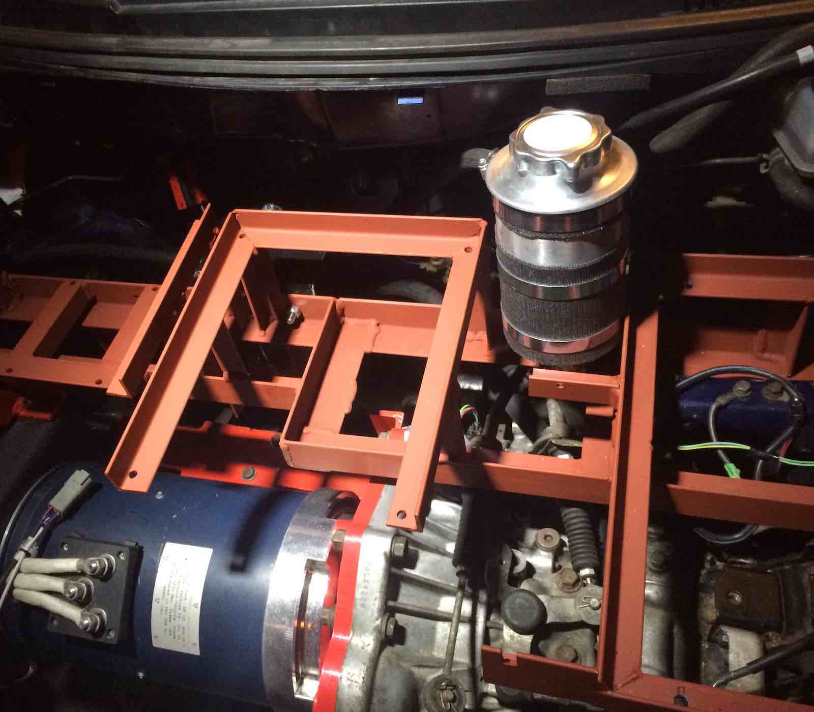
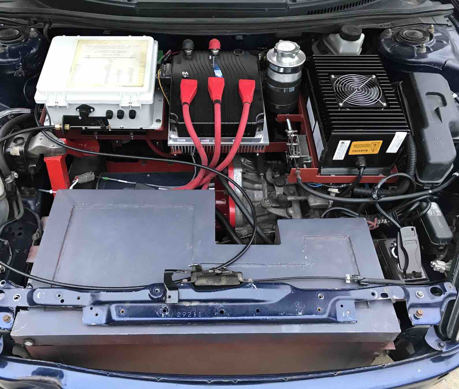
With a number of components still requiring a mounting location, I designed and fabricated a main bracket above the motor. Mounting rails were then welded onto the main bracket to add each remaining component.
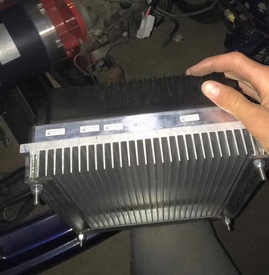
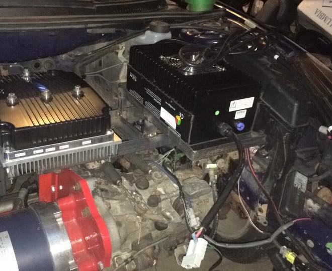
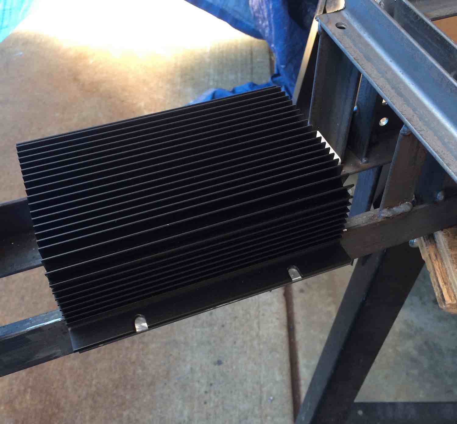
In an AC motor system, the motor controller is responsible for converting DC power from the battery pack to an AC power source (3-phase in this case) and modulate its frequency to control the motor speed. Based on the power needed by the HPEV AC50 motor, the Curtis 1238 motor controller was a great candidate for achieving the vehicle performance goals outlined earlier. A heat sink was installed for air cooling and the controller was installed.
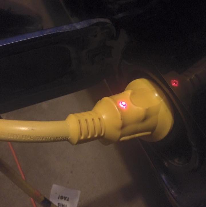
To provide a convenient method for charging the battery pack, an onboard charger was installed that could handle both 120V and 240V inputs.
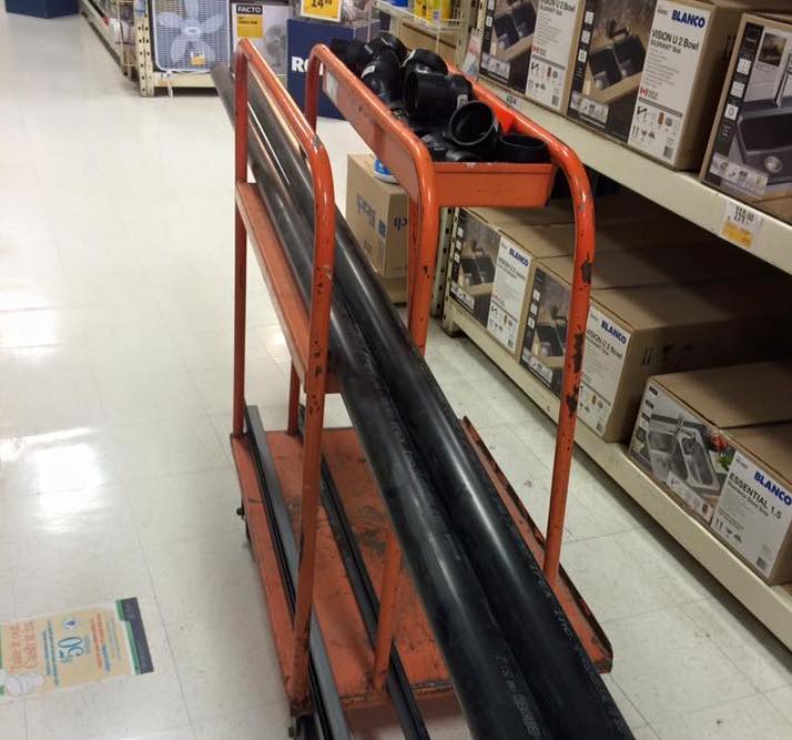
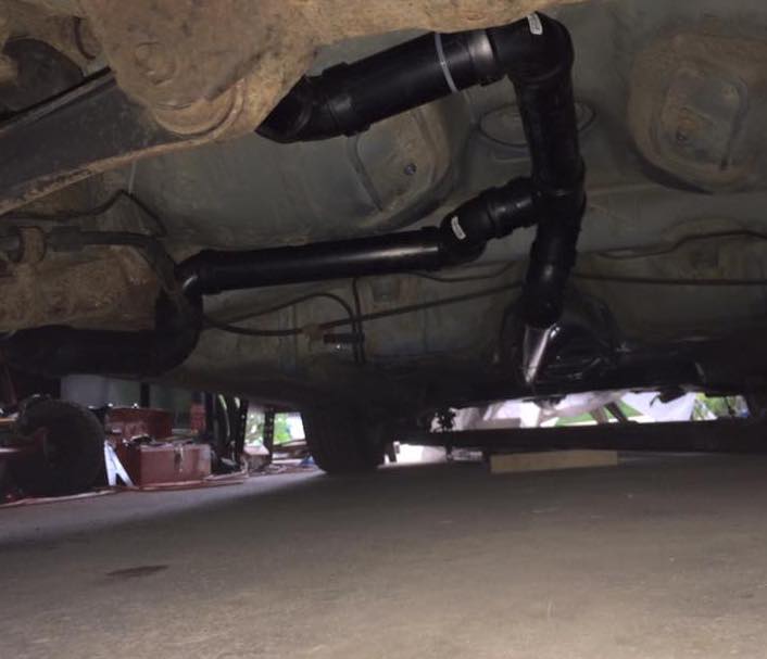
To connect the rear battery box, front battery box, charging port and charger, a conduit from PVC piping was designed. Cables ran between the two battery boxes to complete a high voltage circuit, the charger was wired into the high voltage loop, and finally, the charging port was wired to the charger.
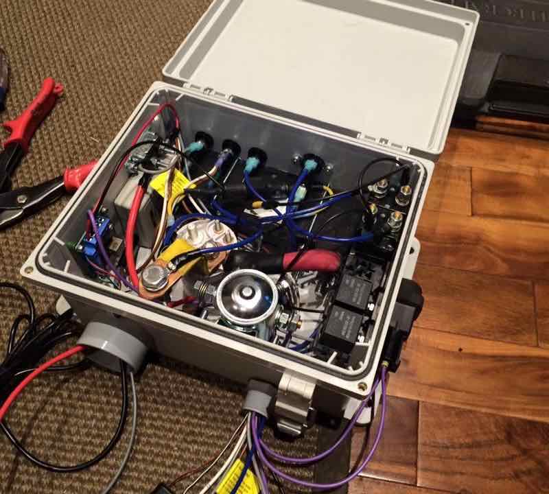
With an ever-growing number of systems needing power controls, safety shutoffs, surge protection, and monitoring, I began wiring a control box that would house each modified systems electrical components.
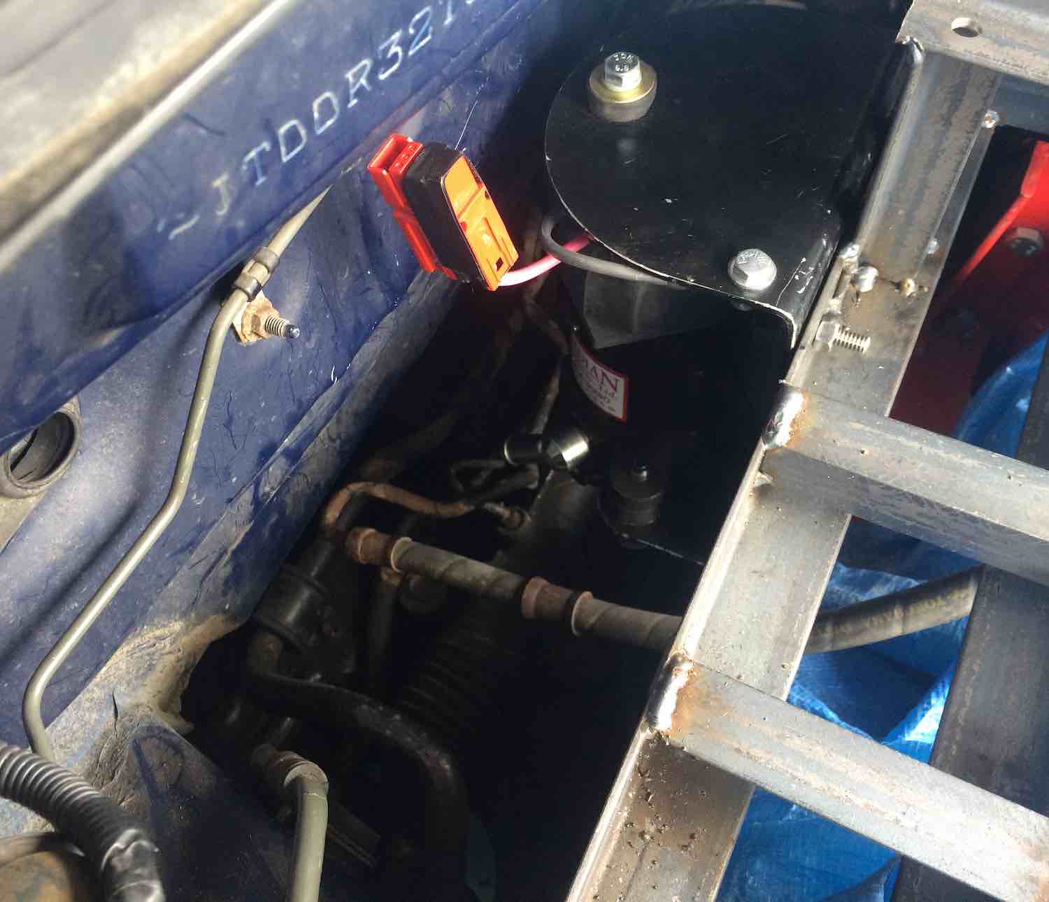
In a combustion powered vehicle, part of the engine's power is used to recharge the vehicle's battery using an alternator. Instead of an alternator to keep the 12-volt battery charged, a DC-DC converter was used to take energy from the 96v system. The 12-volt battery was then hooked back into the vehicles power system to supply each stock 12-volt system with power. The headlights, turn signals, radio, gauge cluster, and so forth were all powered again.
In a combustion powered vehicle, part of the engine's power is used to recharge the vehicle's battery using an alternator. Instead of an alternator to keep the 12-volt battery charged, a DC-DC converter was used to take energy from the 96v system. The 12-volt battery was then hooked back into the vehicles power system to supply each stock 12-volt system with power. The headlights, turn signals, radio, gauge cluster, and so forth were all powered again.
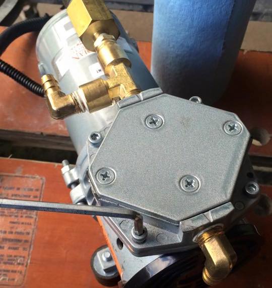
Much like the brake vacuum pump, the original water pump was powered by the combustion engine. To convert the power steering system, an electric hydraulic pump and fluid reservior were added back into the power steering system. Power was routed from the control box with a fuse and contactor built into the system so it would be activated by turning the ignition key. Due to the high power consumption of this system, an additional control switch was added in the cabin to turn off power steering in emergency situations.
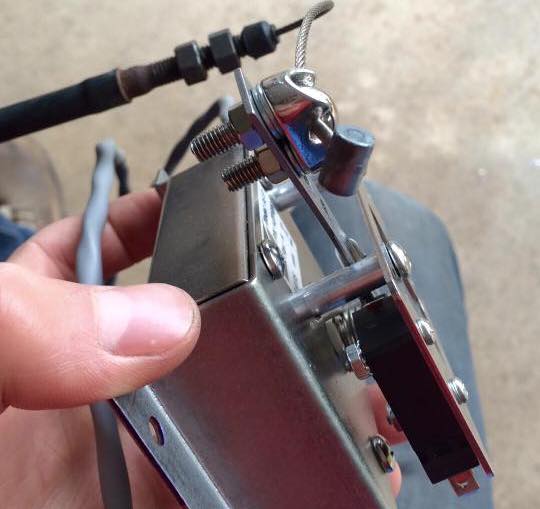
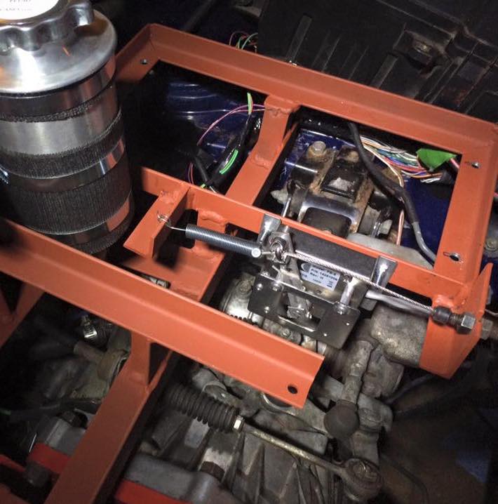
To convert the mechanical throttle pedal movement into an electric signal, a spring-loaded potentiometer was connected to the accelerator cable. With the potentiometers circuit connected to the motor controller, it then maps the range of resistances to a throttle output level.
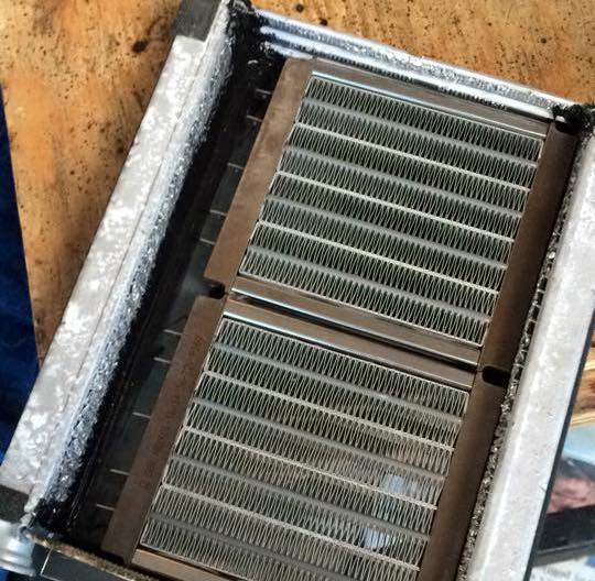
Stock Toyota Celica’s send a loop of coolant that is heated by the engine into the cabin. The fluid then traveled through thin fins to allow heat to dissipate into the air. A fan blowing air through the grid of fins carried the heat into the cabin. Without any liquid cooled components to provide heat, I removed the coolant loop and replaced fins with an electric heater. Power was wired from the control box such that the system would be limited to only operating when the vehicle ignition is on and the fan system is running. A safety override switch was installed to turn off the heating system in an emergency situation.
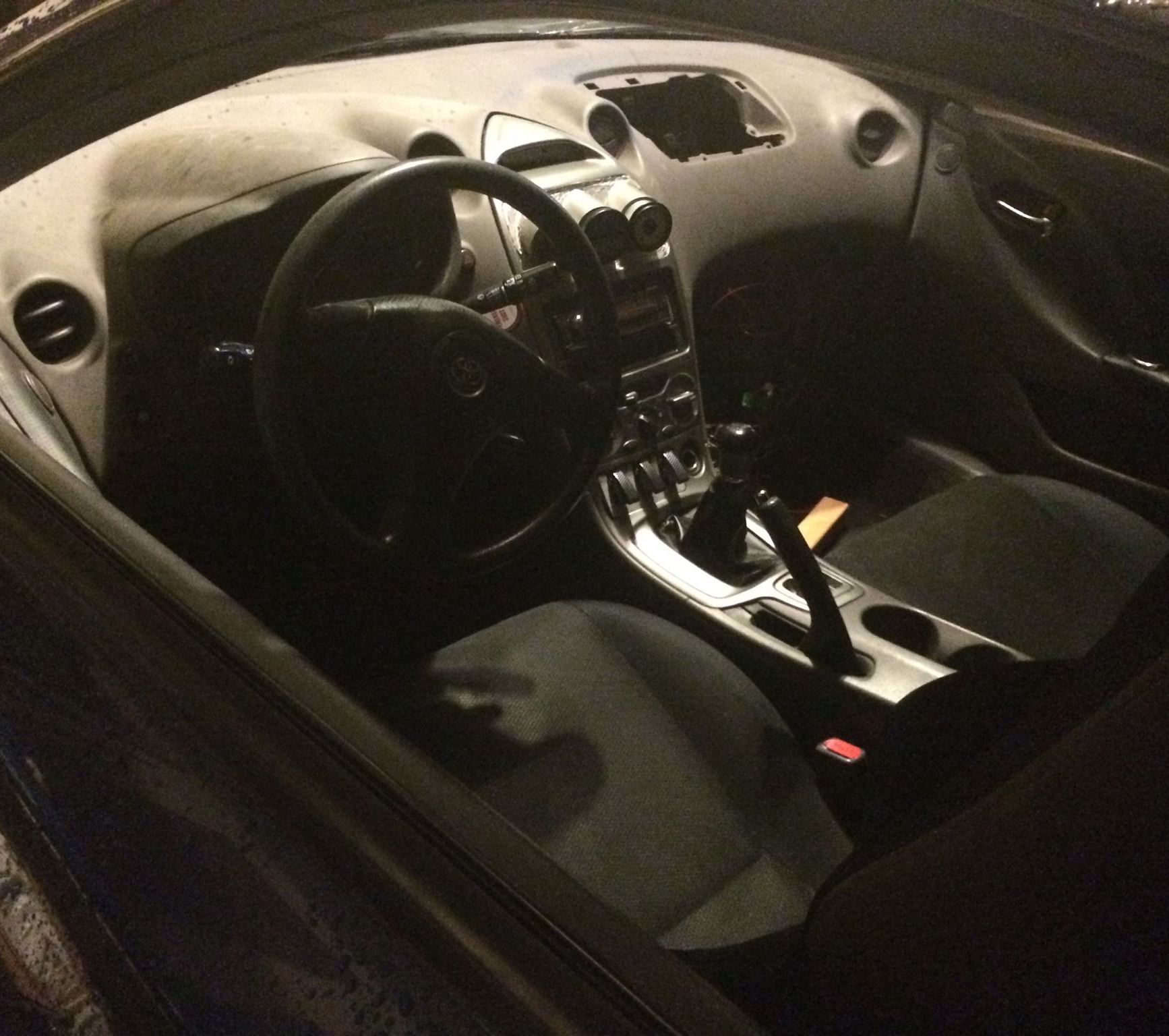
The original gauge cluster was reinstalled to provide accurate speed information, 12v system battery status, and all untouched system warning lights. Three additional gauges were installed to indicate the live amperage draw, check the motor and controllers sensors and settings, and monitor the battery pack.
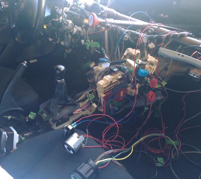
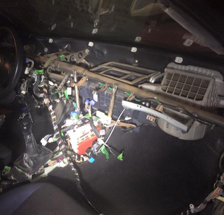
With numerous systems being modified, many wiring harnesses were no longer necessary and could be removed. Additionally, the key switch was modified so that the control box would only be powered when the ignition is turned on.
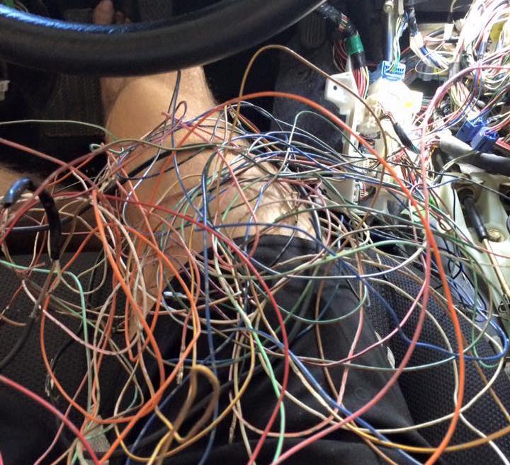
After completing all additional interior wiring jobs, the dashboard was modified to house the new gauge cluster, switches, and an emergency shut off switch.
A safety inertia switch was added to the main control box to break power in the event of a serious collision. With all systems in place, the main battery pack was installed and wired. Each system was inspected, tested independently, and then the car was taken for its very first test drive!
After a few weeks of testing and a couple final tweaks, the vehicle was ready to be used for everyday trips on the streets of Calgary. Years later, the car is still operating as a zero emissions vehicle and being driven regularly.
Did I build a legitimate competitor to current all-electric production vehicles? No, this vehicle is far from production quality. Due to the sheer workload required to complete this project, I was unable to work through enough iterations on my designs, master the trades required to produce ultra aesthetic components, and spend the necessary time on each design challenge to nail the craftsmanship of this product. Overall, the focus of this project was placed on functionality over the aesthetic properties to ensure a working product was reached within the budget constraints.
In terms of technical knowledge, this project pushed me to learn an incredible amount about vehicles and electromechanical design. However, looking back on my experience, it was not the technical knowledge that I appreciate most. I credit this project with teaching me how to deal with ambiguity, decompose overwhelming tasks, and remain persistent and dedicated regardless of where I start in my understanding. Since completing this project, I have focused on continuing to develop a well-rounded design mindset and a diverse toolbox of techniques to bring to new challenges.
I’d like to thank Ryan Smith, Elle Nichols, and Greg Soule for their countless hours of help laboring on the car to ultimately make this project a success. I’d also like to thank Greg Soule and Karen Braun for trusting me with a large financial investment to make this project come to a reality. I wouldn’t be who I am today without this incredible experience.
Portfolio by Matthew Avery Braun Soule